

How To Repair Broken Pins On Sound Board
Easily fix a 'dry' or cleaved solder joint on printed circuit boards
And avert paying for repairs or replacements
Picture the state of affairs where something works just fine one minute, and and then the side by side minute it doesn't. Or maybe a state of affairs where the item in question was working fine when you put information technology away and and so the next time you become to utilise it, y'all get nothing? Sound familiar? Then y'all might have a broken solder joint on a printed circuit board (or PCB for short).
Broken solder joints (don't worry they don't injure…)
These cracked, fractured or broken solder joints are sometimes (erroneously) called 'common cold' or 'dry' joints (but both those terms relate to problems with soldered joints from the start). Cleaved solder joints works for me and is a ameliorate description for this very common electronic failure problem.
Especially electrical items which lead a difficult life; for example, devices that create lots of oestrus, or ones that vibrate or even stuff you plug things into (and out off) repeatedly. All this heat, movement and action weakens the delicate solder joints holding all the gubbins onto the printed circuit lath (PCB's). Especially any joints that were not likewise good in the first place, most of our stuff is mass-produced by the lowest applicant don't forget!
A cleaved solder joint is where the solder connecting the component pivot or leg to the copper runway on the excursion boards becomes damaged. Bad contact with the copper track of course means a poor connection (intermittent issues) or no contact at all (device stops working birthday).
Broken solder joints are often caused by…
- Excess estrus, where the pins/legs and the solder surrounding them aggrandize and contract at unlike rates in use eventually causing smashing and erosion of the solder.
- Fatigue, where the connection between the component pin/leg and the copper track cracks due to repeated move or flexing.
- Weakness in the joint from the start, due to poor soldering technique at the factory (too niggling solder or improper 'wetting' of the joint leading to poor connectivity between the component pin and the conductive track on the PCB).
The likelihood of a soldered joint failing is increased by…
- Intermittent heating/cooling where expansion and wrinkle stresses connections, (power tools for example).
- Frequent and repeated moving of switches and other controls. Oft the 1 used most creates very localised stress, (the max setting on the vacuum cleaner or cooker hood for case).
- Repeated pushing and pulling on plugs or cables physically flexes the joints between the component pins/legs and the circuit board (audio equipment for example).
- Devices that get very hot in use will somewhen endure from one too many heating/cooling cycles. Expansion and wrinkle stresses connections, (panel heaters for example).
- Machines that vibrate a lot because they use a big, fast motor. Vibration stresses the joints betwixt the component pins/legs and the circuit board, (washing machines for example).
- Devices that movement around a lot. Electronics don't like being thrown effectually too much or beingness knocked about as they are a scrap delicate actually, (laptops for case).
Fortunately fixing these broken joints is relatively simple. The hardest role is opening up the car to expose the PCB afflicted. The range of machines and electronic devices is huge so I won't go into detail about how to expose the electronics affected, but suffice to say, you're going to need to undo any screws yous can encounter and remove panels and/or parts that embrace the PCB.
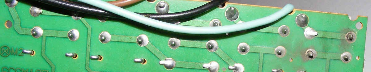
Once you lot can encounter the printed circuit lath inside, go grab a magnifying glass (unless you take optics like a peregrine falcon…) and wait closely at the reverse side of the lath (the side opposite the electronic wizardry). You'll see hundreds of little shiny dots with pins sticking out of them.
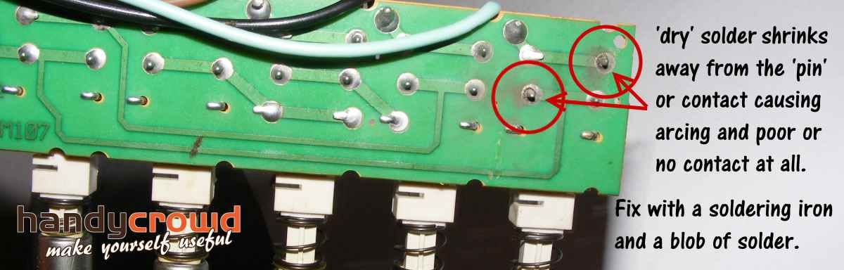
A good solder joint looks nice and shiny whereas failing or 'dry out' solder joint looks irksome and crusty. You might fifty-fifty see a band or fissure around the pivot or leg.
The set up…
The fix is to re-solder any bad joints with fresh solder. Provided the arcing or intermittent employ hasn't damaged whatever small electrical components, generally this fixes the trouble. Just showtime; the damaged joint has probably left the old solder in a dingy or even sooty condition due to arcing (sparks acquired by a poor connection). Gently clean this abroad physically using a cotton bud or an old toothbrush. Dipping the bud/brush (and taking off the excess) into a light solvent (preferably isopropyl booze) works on more than stubborn dirt (you tin can utilize water to dampen a cotton wool bud in a compression, but brand sure everything is bone dry before switching on over again).
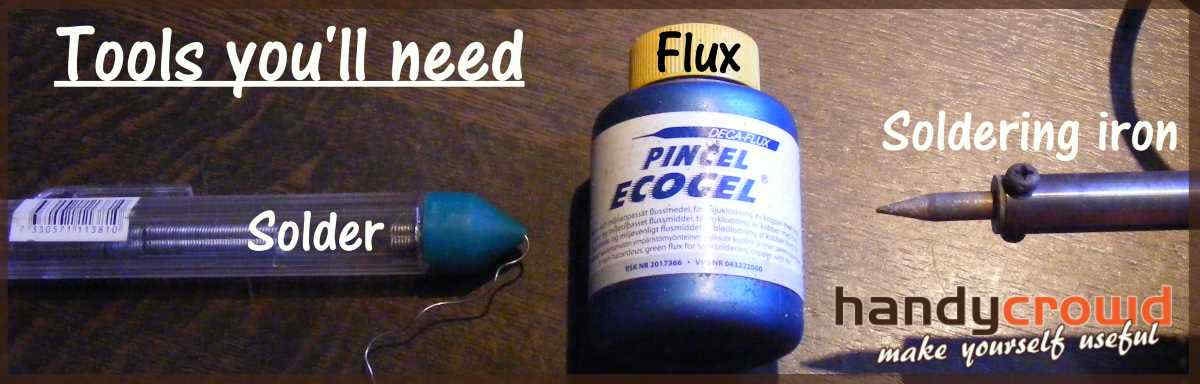
There are two important things to think when trying this repair. First, always utilise a flux when soldering. This magical paste will chemically clean the articulation making the solder 'stick' much better. In fact, soldering without it is very difficult for the amateur (trust me on this, I know!). 2nd; soldering irons get very hot then yous need to piece of work very speedily to avoid dissentious the component.
How to solder a dry out joint…
Become the iron really hot, wipe some fresh solder onto the tip and wipe it off again by drawing the tip across a damp sponge (this cleans or 'tins' the tip). Once you're ready, touch the screaming hot tip to the component pin/copper on one side and touch the new solder to the other. Lift off the iron as presently as you see the solder cook (it runs and turns moisture and shiny). It should only accept a 2d or two… Repeat on all the ones that look suspect. It's very common to encounter several that are poor. Wipe away whatever excess flux that sits around the new joints once they've cooled downward.

Call up you heat the joint non the solder… Heat, feed in the new solder and and then lift both speedily away.
All done? Cool, now you can re-assemble the thing and tentatively switch it back on….. with a bit of luck y'all've fixed it and if not, well, it does happen. Only remember it was cleaved, probably beyond economic repair before y'all started, so there was admittedly nothing to lose by trying this repair. Recollect that and chalk it downward to experience.
If you demand more than assistance on the soldering side, take a look at the links below and of course my quick video (you tin can turn your speakers off if you like, the music is a fleck much!).
Click here to learn how to solder and hither to learn how to solve some common soldering problems.
Stay well
Ian
Broken solder joint update:
Even after more than xxx years I even so get surprised from time to time. The 'star' lamp fitting in the above video is one of a pair and lo and behold the second ane started some erratic behaviour this week besides, a mere two months after the first i! Amazingly consistent build quality on these very old lamps. Impressed? Little fleck!
Hither is a couple of close ups of the offending dry solder joints. The pins are clearly loose and the arcing has damaged the board. Sadly, the PCB looks a niggling too far gone to be safety this fourth dimension, but I might give it a go and keep a close heart on it to ensure it's withal safe.
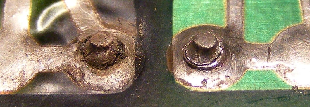
Clear to meet the damaged PCB around the left hand pin caused by arcing around the dry solder joint…
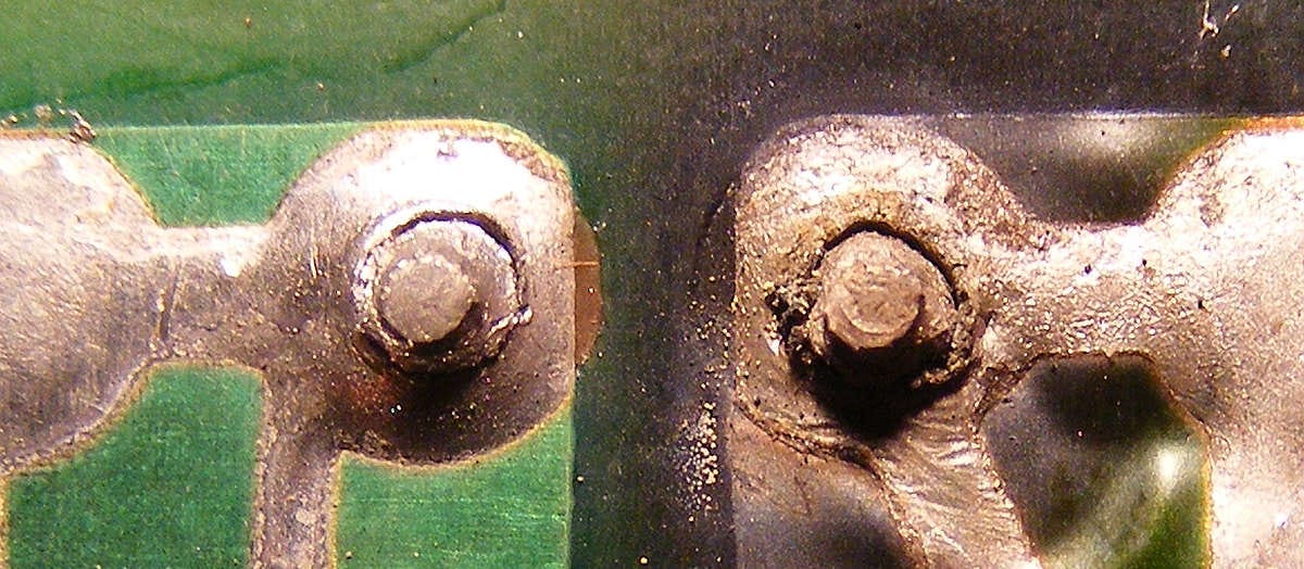
Rings of broken solder are piece of cake to meet close upwards… classic failed solder joints due to overheating.

How To Repair Broken Pins On Sound Board,
Source: https://handycrowd.medium.com/easily-fix-a-dry-or-broken-solder-joint-on-printed-circuit-boards-50c53cc974a1
Posted by: pattersonglachind.blogspot.com
0 Response to "How To Repair Broken Pins On Sound Board"
Post a Comment